Lockdown mode in ESXi

– Lockdown mode disables all direct root access to ESXi host.

– It disable SSH access to ESXi host.

– Also user will not be able login through vsphere client.

– By default, local user does not exist on the ESXi host.

– So before enabling Lockdown mode, make sure that, local user (non-root) has created on the ESXi host.
How data transfer across a network

  • When a host transmits data across a network to another network or device, the data goes through Encapsulation.
  • Encapsulation is a process of wrapping protocol information to the data.
  • At each layer PDU is attaches to the data and passed to next layer.
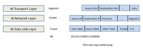
  • When the data stream handed to the transport layer, which actually setup virtual circuit with receiving device by sending over a sync packet, it attaches TCP header (PDU) to the data field. This complete piece is now called segment.
  • Each segment is sequenced so that at receive end it helps them in rearranging once received.
  • Each segment is then passed to the Network Layer for network addressing and routing through internetwork.
  • Network Layer adds control header (IP Header) to the segment. This piece is called packet or datagram.
  • On receiving end, network layer and transport layer work together to rebuild a data stream.
  • Data link layer encapsulates each packet into frame and frame header contains hardware address (mac address) of source and destination.
  • If the destination device is on the other network, frame is then sent to router.
  • To put this frame on the network, it must be put into a digital signal.
  • Since frame is a logical group of 0’s and 1’s, the physical layer is responsible for encoding these digits into digital signals.
  • The receiving device will synchronize on the digital signal and extract (decode) signals the 1’ and 0’s from the digital signal.
  • Receiving device rebuilds the frame, the run a CRC (Cyclic Redundancy Check) and match against frames FCS field.
  • If it matches, Packet is pulled from frame and rest of the part discarded. This process is called de-encapsulation.
  • This packet is then passed to the network layer, where the address is checked.
  • If address matches, the segment is pulled from the packet and remaining part is discarded.
  • The segment is pulled from the packet at transport layer, which rebuilds the data stream and acknowledges to the transmitting station that it received at each piece.
  • Data stream is the handed to the upper-layer application.

Addressing

Protocol Data Units (PDU)

  • When a host transmits data across a network to another device/host, the data goes through Encapsulation.
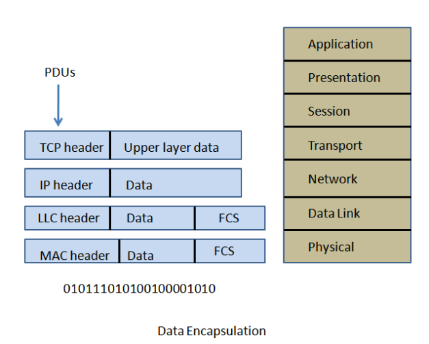
  • In Data Encapsulation, It wrapped with Protocol Information at each layer of the OSI model.
  • PDUs hold the control information attached to the data at each layer of the model.
  • They are usually attached in front of the data or at the end of the data.
  • Each PDU attaches to the data by means of encapsulation at each layer and each has specific name depending on the information provided in the header. For example, PDU created at Transport Layer called TCP header, PDU created at Network layer called IP header etc.
  • This PDU information is ready only by the peer layer on the receiving device.
  • Once PDU is read, it is stripped off and the data is then handed to the next layer up.
  • Below fig shows PDU and Data encapsulations happnes at each layer of the OSI model.


Image

Ethernet Addressing

  • It Uses Media Access Control address (MAC) burned on every ethernet card
  • It is 48 bits (6 bytes) written in Hexadecimal Format
  • Higher 24 bits are OUI (Organizationally Unique Identifier) and it is assigned by IEEE to each vendor. And it is unique among all the vendors
  • High-order bit(47th bit) of OUI is the Individual/Group (I/G) bit. When it is 0, we can assume that address is the MAC address. When it is 1, we can assume it is broadcast or multicast address in Ethernet.
  • Next bit of OUI (46th bit) is the Global/Local bit (G/L) also known as (U/I). When it is 0, it represent Globally administered address (as per IEEE) and when it is 1 it represent locally governed and administered address.
  • The low-order 24 bits are vendor assigned bit. This portion commonly start with 00:00:00 for the first ethernet card and continues till FF:FF:FF for the last ethernet card (total cards : 1,67,77,216)

    Ethernet Addressing shown Below.

Image